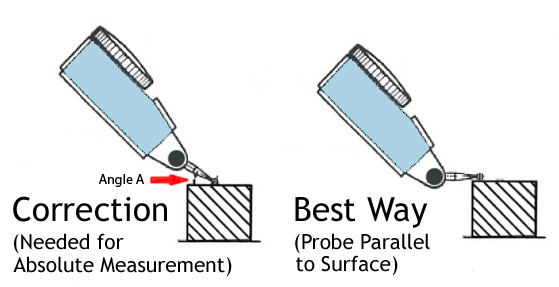
The Dial Test Indicator is one of the most popular and most commonly misused measuring tools. The fact that the test indicator’s contact point moves in an arc instead of a straight displacement is the root of the problem. An issue known as cosine error occurs when the contact point is not parallel with the surface to be measured*.
This is not much of a problem when using the test indicator to make a comparative measurement. For instance, making sure that the run-out of a shaft is the same as another. However, if an absolute linear displacement measurement is needed, cosine error is a big problem unless a corrective multiplier is used.
To calculate the correction, a simple formula that you may remember from your high school geometry class can be used!
Cosine A = Adjacent/Hypotenuse
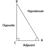
This calculation is appropriate because the test indicator’s contact point in relation to the test piece/displacement vector (with the tip bent improperly) forms a right triangle.
These correction factors can be determined simply by entering the angle and tapping the cosine key of a scientific calculator.
| Angle A | Correction Factor |
| 10° | .985 |
| 20° | .940 |
| 30° | .866 |
| 40° | .766 |
| 50° | .643 |
| 60° | .500 |
Example:
Angle 40°
Indicator Reading .002”
Correction Factor .766 (cos 40°)
.002” x .766 = .0015”
This calculation can be used for any length contact point.
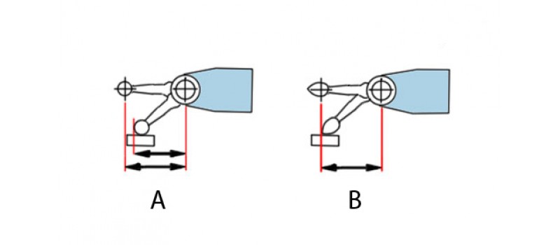
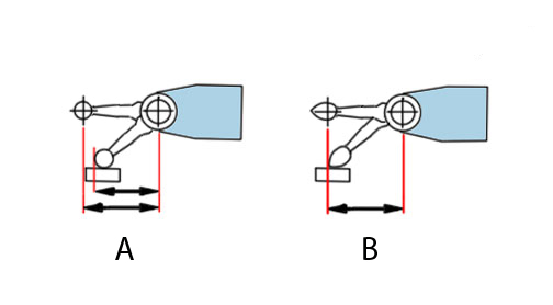
Pear shaped contact points eliminate cosine error up to 36 ̊. I like the drawing of the contact point below because it shows another way of thinking about cosine error, that being the relationship of the distance between two centers. If the distance between the two centers is reduced, an error will occur. The pear shaped contact allows for the centers distance to remain the same as it is bent to preserve the proper contact point length. Pretty neat!
Finally, we have fielded many calls from people looking to buy a new contact point for an existing test indicator. This is not a problem but do not change the overall length of the contact point! If the contact point is longer than the original, the gage will become less sensitive to a linear displacement and if the contact point is shorter it will become more sensitive. If you are not sure what the contact point length is for a correct replacement, simply measure from the shoulder of the contact point (do not include the thread) to the tip of the ball. That is how manufacturers specify their lengths. Also, since most test indicators use metric threads, you can measure the major diameter of the thread with a caliper and determine the thread size. M1.4 or M1.6 which would be 1.4mm or 1.6mm diameter respectively.
* Interapid and Bestest by Brown & Sharpe /Hexagon are known exceptions and are designed work with the contact point bent at a 12 ̊ angle to the part.
Comments